How to debug the PCB antenna
Introduction
PCB antennas are becoming increasingly popular due to their compact size and low cost. However, tuning them correctly can be challenging, especially for novices. This article aims to provide a step-by-step guide on how to tune a PCB antenna to achieve optimal performance.
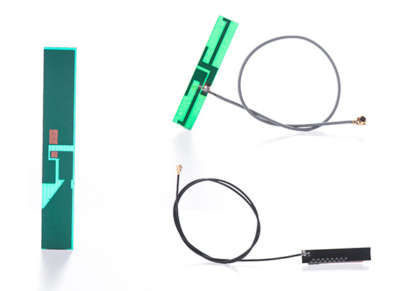
Step 1: Determine the Center Frequency
The first step in tuning a PCB antenna is to determine the center frequency. This can be easily done using a network analyzer or spectrum analyzer. Once you have determined the center frequency, it is essential to verify that the frequency range of the analyzer is sufficient to measure the antenna's performance over the complete frequency range you will be using.
Step 2: Simulate the Antenna Performance
Before building the antenna, it is crucial to simulate its performance using a 3D electromagnetic simulation tool. This will help you to understand the expected radiation pattern and achieve the desired gain and impedance matching. In addition, it will help you identify any issues that may need to be addressed in the design.
Step 3: Build the Antenna
Once you have determined the center frequency and simulated the antenna performance, it is time to build the antenna. PCB antennas are typically printed on a substrate layer, and the antenna design is optimized by changing various parameters such as the trace width, length, ground plane, and via positioning.
Step 4: Test the Antenna
After building the antenna, it is essential to test its performance using a network analyzer or spectrum analyzer. These instruments help in measuring the antenna's impedance matching, gain, and radiation pattern. In addition, you can also perform a VSWR (Voltage Standing Wave Ratio) test to verify the antenna's bandwidth.
Step 5: Tune the Antenna
After measuring the antenna's performance, you may need to tweak its design to achieve the desired performance. The following are some common tuning techniques that can be used to fine-tune the antenna:
1. Adjust the trace width
Changing the trace width is a simple way of tuning the antenna's impedance matching. If the antenna's impedance is too high, increasing the trace width will reduce the impedance. Conversely, if the impedance is too low, reducing the trace width will increase the impedance.
2. Change the ground plane size
The size of the ground plane can also affect the antenna's performance. A larger ground plane can increase the gain and reduce the antenna's impedance, while a smaller ground plane can lower the gain and increase the impedance.
3. Adjust the antenna length
The antenna's length can also be adjusted to achieve the desired performance. By increasing the length, the antenna's gain can be increased, and the bandwidth can be improved. Conversely, by reducing the antenna's length, the impedance can be increased.
4. Change the feed point location
Changing the feed point location is another way to tune the antenna's impedance matching. By moving the feed point, you can adjust the impedance to match with the transmitter's output impedance.
Conclusion
PCB antennas are becoming increasingly popular due to their compact size and low cost. However, tuning them correctly can be challenging. This article provides a step-by-step guide on how to tune a PCB antenna to achieve optimal performance. By following these steps, you can design an antenna that meets your performance requirements and maximize your wireless device's range and reliability.
